Thanassis G. Giokas
Knowing not how to listen, they do not (know) how to speak.
HERACLITUS
Ελληνικά English

ELECTRONIC COMPONENTS AND MATERIALS TEXTBOOK VOLUME II

CHAPTER 7 - PIEZOELECTRIC CERAMICS

Download here a part from this Chapter.

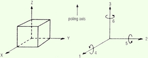
Before advancing to the attributes, it is necessary toy provide the information required so as to be completely understood. In Figure below you can see the design of the axes of the piezoelectric materials. The axes X, Y, Z are symbolically replaced by the numerals 1, 2, 3 and the rotation around them by the numerals 4, 5, 6 respectively. These numbers are used as indexes to some attributes, as for example ε11T represents the piezoelectric permeability with shift and electric field in address 1, with fixed mechanical stress. Similarly, k15 represents the electromechanical coupling coefficient in address 1, with rotation (distortion) in 5 (shear mode).
In Table we show the common vibration modes of piezoelectric materials, the resonance frequencies and the constant symbols of the materials. In every case, the addresses of E and P are parallel, except for the last. In the radial mode, the polarization P is oriented according to the disc thickness. In the Longitudinal mode, the vibration is vertical against the polarizations and there is a point of resonance. In the longitudinal mode the vibration is oriented along the polarization with a point of resonance. In the thickness mode, the vibration is parallel to the polarization and there are many points of resonance. Finally, the shear mode (shear distortion without variations n the volume) is the result of the verticality of E and P.

Download here a part from this Chapter.


Adobe Acrobat Reader is needed to view the file above.